4G Module
Product features
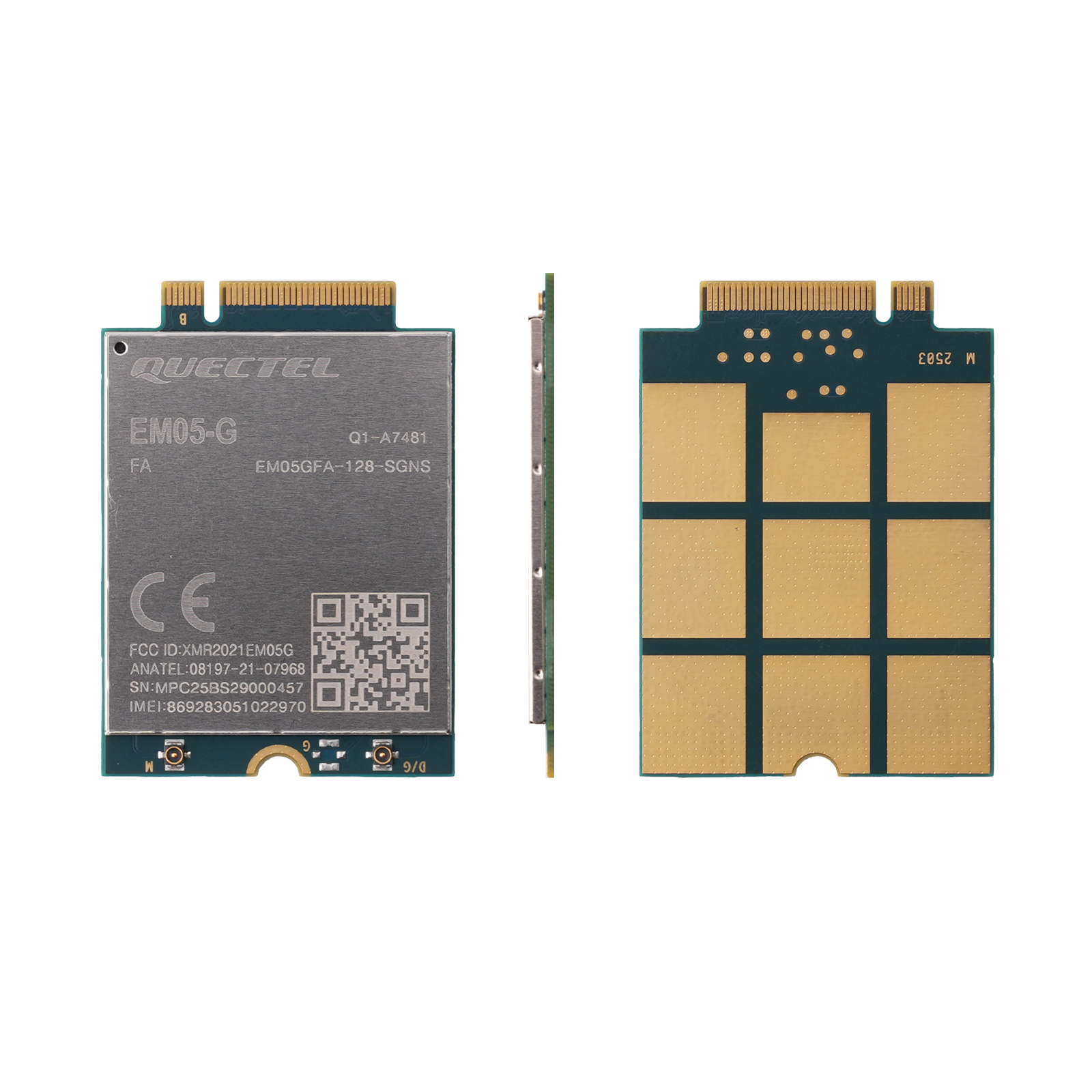
Quectel EM05-G is an LTE Cat 4 module designed for IoT/M2M applications. Featuring M.2 form factor, it supports multi-mode networks (LTE-FDD/TDD, WCDMA, CDMA, etc.) and is suitable for industrial routers, vehicle-mounted equipment, digital signage, and similar scenarios. Key features include:
- Global Band Coverage:
Supports multiple bands including LTE-FDD/TDD and WCDMA, compatible with major global operators. - High-Speed Transmission:
Maximum downlink rate: 150 Mbps
Maximum uplink rate: 50 Mbps - Multi-OS Compatibility:
Supports Windows/Linux/Android drivers with integrated DFOTA and optional GNSS. - Industrial-Grade Reliability:
Operating temperature: -30°C to +70°C
Extended temperature range: -40°C to +85°C
Model Comparison
| Type | Region/Carrier | Supported Network Standards | Dimensions (mm) | Temperature Range |
|---|---|---|---|---|
| EM05-CN | China、Thailand、India | LTE-FDD/TDD、WCDMA、CDMA | 30.0×42.0×2.3 | -30°C~+70°C |
| EM05-E | Europe、Australia、New Zealand | LTE-FDD/TDD、WCDMA | 30.0×42.0×2.3 | -30°C~+70°C |
| EM05-G | Global | LTE-FDD (B1/B2/B3/B4/B5/B7/B8/B12/B13/B14/B18/B19/B20/B25/B26/B28/B66/B71) | 30.0×42.0×2.3 | -40°C~+85°C (expansion) |
Specifications
| Parameter | Specification |
|---|---|
| Supply Voltage | 3.135V ~ 4.4V (Typ. 3.3V) |
| Operating Current (LTE-FDD) | Max. 1005 mA (Band B71) |
| Operating Temperature | -30°C ~ +70°C (Standard) -40°C ~ +85°C (Extended) |
| Storage Temperature | -40°C ~ +90°C |
| Antenna Interface Impedance | 50 Ω |
| USB Interface | USB 2.0 High-Speed (480 Mbps) |
RF Performance
| Network Standard | Downlink Rate | Uplink Rate | Supported Band Examples |
|---|---|---|---|
| LTE Cat 4 | 150 Mbps | 50 Mbps | B1/B2/B3/B4/B5/B7/B8/B12/B13/B14 etc. |
| DC-HSDPA | 42 Mbps | 5.76 Mbps | WCDMA B1/B2/B4/B5/B6/B8/B19 |
Interface Description (M.2 Key B)
Pin Definition Table
| Pin Type | Pin Name | Function Description |
|---|---|---|
| Power | VCC | Main power input (3.3V) |
| Ground | GND | Ground |
| USB Interface | USB_DP/USB_DM | USB 2.0 differential data lines (90 Ω impedance matching) |
| SIM Interface | USIM1_DATA/CLK | 1.8V/3.0V SIM card data and clock signals |
| Control Signal | RESET# | Module reset (active low) |
| RF Interface | ANT_MAIN | Main antenna interface (LTE/WCDMA) |
| GNSS Interface | ANT_DRX/ANT_GNSS | Diversity Receive/GNSS antenna interface (Optional) |
Usage Instructions
Key Hardware Design Points
-
Power Supply Design
- Requires a regulated 3.3V power supply with transient voltage ≤4.7V
- Reference circuit must include filter capacitors (e.g., 220μF tantalum + 100nF ceramic)
-
Antenna Connection
- Main antenna (ANT_MAIN) and diversity antenna (ANT_DRX) require 50Ω RF cables
- GNSS antenna must support L1 band (1559~1609 MHz)
-
SIM Card Interface
- Supports 1.8V/3.0V SIM cards - place close to module to minimize signal interference
- Hot-swap detection pin (USIM_DET) requires resistor voltage divider protection
-
Firmware Upgrade
- Update firmware via USB using DFOTA or QFlash tools
Physical Specifications
Dimensional Description
- Dimensions: 42.0 mm (L) × 30.0 mm (W) × 2.3 mm (H)
- Mounting Holes: 4 × M2 threaded holes - recommend thermal pad for heat dissipation